Few years ago I modified a salvaged ATX power supply to a fixed voltage bench power supply. It was very useful, I still use it, however it comes a time when you need other voltages than some fixed voltages (eg. 3/5/12V). Nevertheless you might even need to be able to limit the current drawn by the load so obviously a computer ATX PSU is not what you need. What you need is a variable power supply. The cheapest variable power supply that one can get from eBay starts from $50 and can go as far as $1000 or more. For a weekend hobbyist that would be an overkill. Since a hobbyist why not building one for less than $25 instead? First it would be fun and second, since it is made by ourselves we would know how to fix it or upgrade it at anytime. So let's get started!
Features
it should be portable so it would be nice to have a pluggable power cord instead one soldered/connected permanently.
it should be easy to start/stop so a switch button is a must; preferably one with a light indicator
it should contain a short circuit protection so a 5A fuse holder is also a must
it should allow us to connect the VCC/ground with easy so a pair of banana binding posts are preferable
it should allow us to tune the voltage and amperage so 2 variable potentiometers would be required and preferably a pair of control knobs
it should display the voltage/amperage so a LCD ammeter voltmeter would be exactly what we need
an enclosure/case for the project is also required, plastic/Aluminium would be the best
it should allow us higher voltages as 24V or 30V and minimum 1A so a 30W AC-DC transformer is a minimum
it should be able to step-up or step-down the voltage from to 0-30V; although we could build the voltage buck/boost converter from scratch it would be cheaper/effective to buy an off-the-shelf board that does exactly this
optionally it may provide some outputs for fixed voltages like 3.3V or 5V which are handy when working with micro-controllers, Arduino, charging a smartphone, etc
Bill of Material
0-30V 10A buck/boost converter: LTC3780 regulator for $10
100-240VAC to 12VDC @ 5A (60W) power supply for $5+
10A 250V Inlet Plug Fuse Switch Power Supplys Socket 3 Pin for $1
100V 10A LCD voltmeter ammeter for $2.5
1 pair banana binding post for $0.5
200x120x75 mm enclosure box for $5
10pcs knobs for rotary taper potentiometer for $0.7
optionally a 1.8A, 1-17V buck converter for $0.5 (or 5pcs @ $2) that would be use for providing fixed voltage outputs for small current loads
Please note that if you buy a larger quantity the price per unit is smaller than what was estimated above. Usually I buy at least 5/10/20/100 pieces for those components that I know I might use in different projects (eg. switches, fuses, binding posts, pots, etc)
Components Wiring
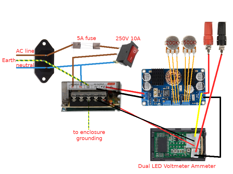
Not an artistic draw but something that might help you to understand the components involved and the wiring between them. So let's start following the whole circuit:
powering the AC-DC power supply
the AC line goes to the 5A fuse which later goes to the pin 1 of the power switch
the AC neutral goes to the pin 3 of the power switch and also to the AC-DC power supply's AC input Neutral terminal
the pin 2 of the power switch goes later to the AC input Line terminal of the AC-DC power supply
the AC Earth goes to the AC-DC power supply's Earth terminal
powering the LTC3780 regulator:
the DC positive output goes to the LTC3780 positive Input terminal
the DC negative output goes to the LTC3780 negative Input terminal
powering the digital LCD voltmeter-ammeter:
the thin red/black wires from the 3-pins connector represents the digital LCD voltmeter-ammeter DC power supply; they can be connected directly to the AC-DC power supply's DC output terminals
connecting the digital LCD voltmeter-ammeter:
connect the yellow wire of the LCD voltmeter-ammeter's 3-pin connector to the LTC3780 Output's positive terminal
connect the LTC3780 Output's positive terminal to the banana binding post assigned for the positive DC voltage
connect the thick black wire of the digital LCD voltmeter-ammeter's 2-pin connector to the banana binding post assigned for the negative DC voltage
connecting the rotary potentiometers:
replace the built-in 500K fixed potentiometer for the voltage control (CV) with a 500K rotary potentiometer
replace the built-in 200K fixed potentiometer for the current control (CC) with a 200K rotary potentiometer
More or less this is all that should be done. Make sure you enclose all these connected components inside your project box enclosure by using fixing screws, hot glue, thermal paste and/or whatever you think is needed in order to have a solid safe box for the project.
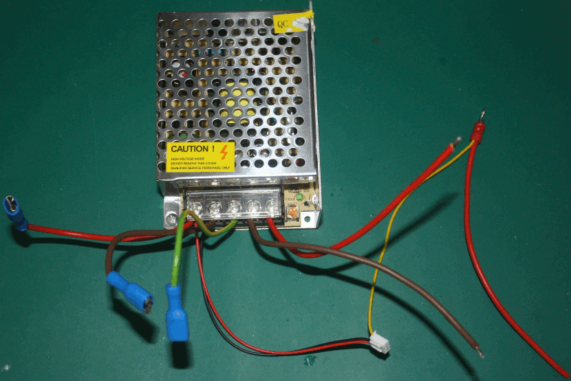
Below are few of the pictures I took while connecting and/or assembling the components:
the AC-DC power supply wiring
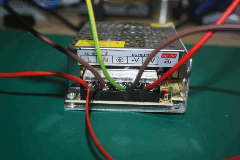
..and a close-up that emphasizes which wire goes where:
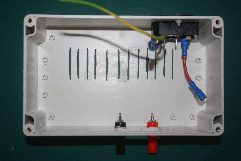
the project enclosure box (the ventilation "holes"); I used a dremel to make few cuts but a drill can be also used for drilling holes instead
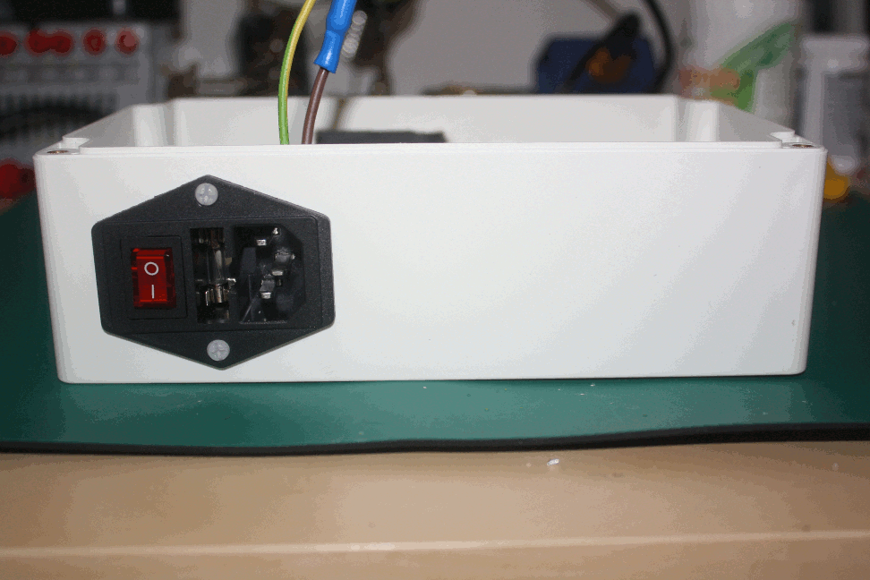
the AC power socket with inline fuse and power switch
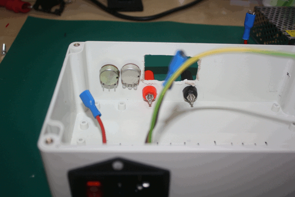
the banana binding post and the rotary potentiometers in place
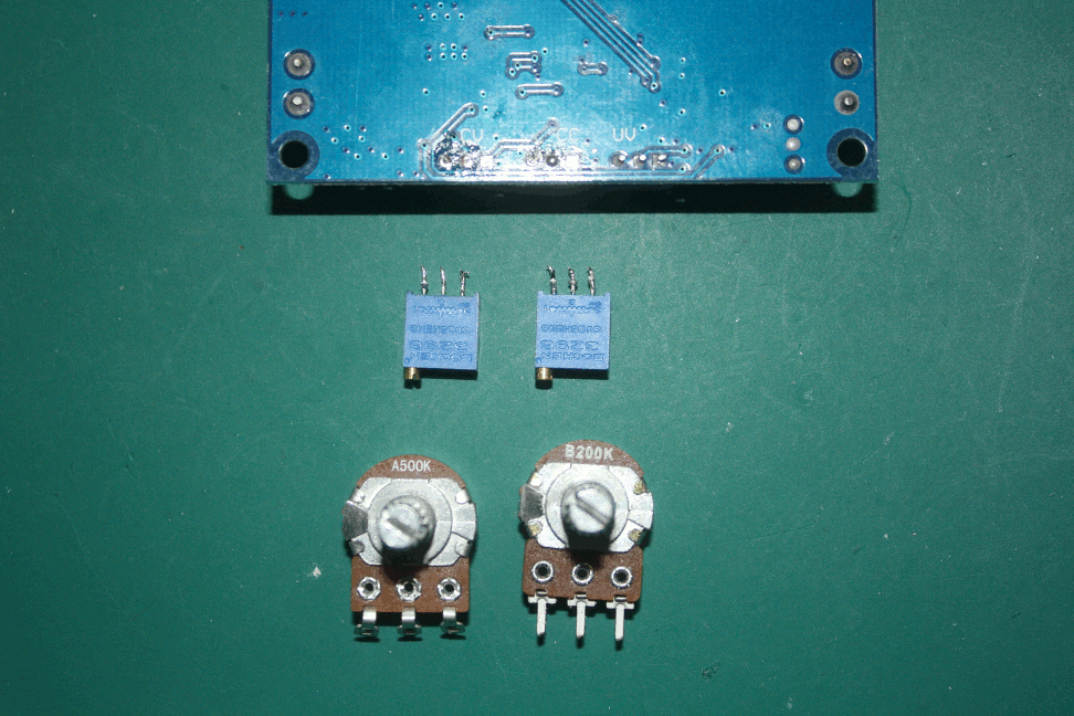
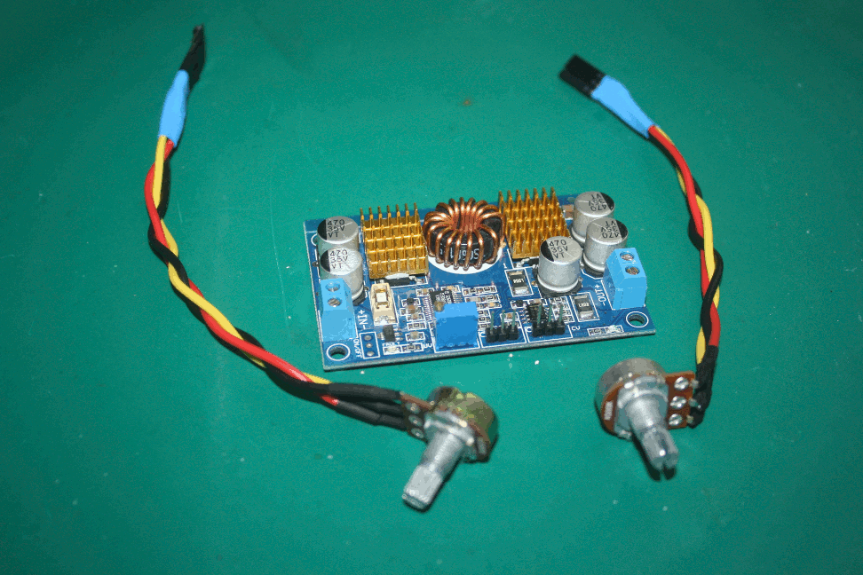
desoldering and replacing the LTC3780 CV and CC built-in potentiometers with our rotary potentiometers
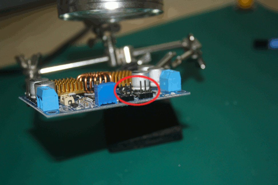
soldering 3-pin headers for connecting the rotary potentiometers
preparing the rotary potentiometers for plugging-in to the LTC3780 board's 3-pin headers
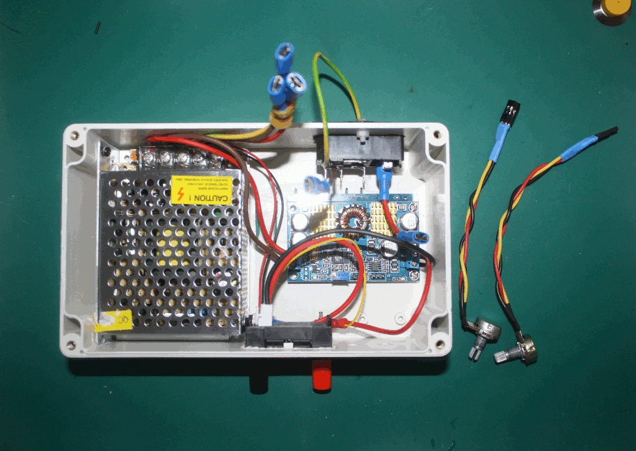
the project's components almost connected
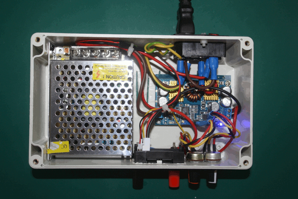
with the rotary potentiometers connected too the box should be ready for the test-drive
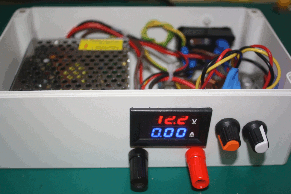
yes, it works!
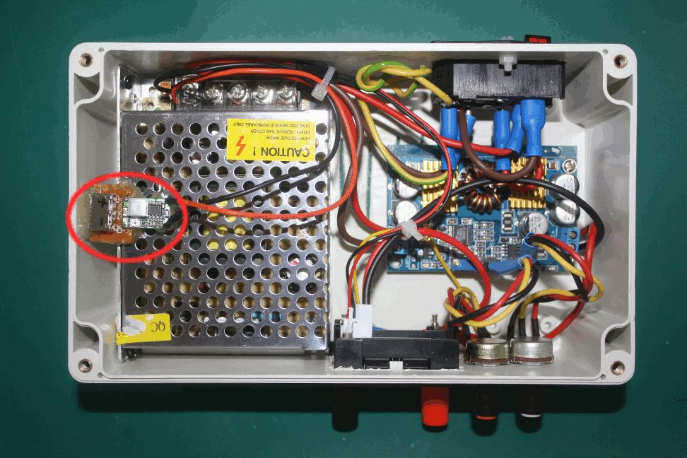
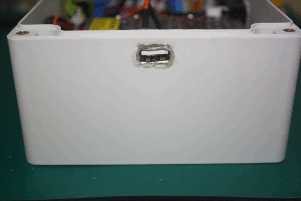
first upgrade: a 5V USB port powered by a 5V @ 1.8A buck converter
the USB port glued (now has a very strong grip)
What's Next
I intend to control the enclosure's temperature by using a 40mm x 40mm 12VDC fan together with a simple fan controller which basically uses a MCP9700A analog temperature sensor + a MOSFET amplifier. When the internal temperature raises so does the fan speed and vice-versa.
Comments
1 comment
Is it possible to connect saparate ammeter and volt meter to both potentiometer? So we can see that what volt and ampiure we set for the load..
Leave a comment